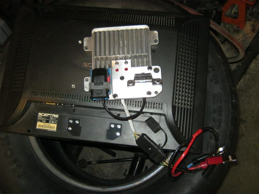
yup sloppy ass ****. i clipped the terminal wires off flush with the connector, and jammed a pick in em to open em up (the bolt free 02 conn still has several that arent opened up to keep the connector held in place.
im just pointing out that if your finding pcm connectors that arent lining up, just use the diagram for the donor, snip wires, be on your way. your reworking the **** out of a connector, labor that should go towards more important parts of the project.
its a diode cluster rectifier...not much else to say, its cheap, wire up the output to offboard, put inputs to alligator clips for the battery. dont even have to label em (id did mine since my led droplights use the same connector and they run off a car battery quite well (it also allows me to use the offboard with my lights 12v 110v power supply and connector...kill 3 birds, one connector
if ya keep the switches, make sure they are well protected, inside a recess. my switches can only be turned off by a finger sized object. if someone dropped a cylinder head on it it would only turn the switch on, and never off.
to each their own
btw if you want the lazy way AND the fat wires, look for the 98 and earlier pcm connectors...them 96's actually used proper sized wire before gm cut the costs by cutting the copper down, since cars required more and more wire each year.
i cant be the only guy that noticed the pcm pinout differences and actually investigated the pcm pin connections am i?


