Thread: How To: Build an offboard PCM interface

Results 1 to 20 of 43

Hybrid View

Previous Post Previous Post   Next Post Next Post
  1. #1 Re: How To: Build an offboard PCM interface 
    Solving problems BrandonHall10's Avatar
    Join Date
    Mar 2014
    Location
    Tucson
    Posts
    3,192
    Thanks (Received)
    10
    Likes (Received)
    146
    Dislikes (Received)
    3
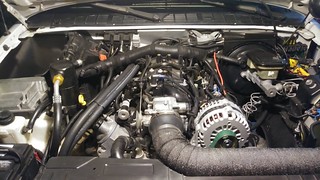
    As far as leaving wires in, or taking them out... To each their own. There is no wrong way. God bless America, we get to do what we want. The only reason to pull them out, is to not have to look at them. Aesthetics. That is exactly my reason. If someone wants to leave them in and just cut them short, I'm not mad.

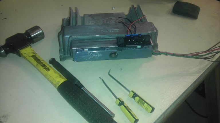
    Tell me more about this 4 diode rectifier thing.
    Reply With Quote  
     

  2. #2 Re: How To: Build an offboard PCM interface 
    Solving problems BrandonHall10's Avatar
    Join Date
    Mar 2014
    Location
    Tucson
    Posts
    3,192
    Thanks (Received)
    10
    Likes (Received)
    146
    Dislikes (Received)
    3
    Well, I think I got it. I used some different colors, but I managed to keep the grounds black and the 12v+ red. All my data lines are green and my switched 12v is purple.


    Thanks Scotty!!

    Quote Originally Posted by BillBoost37 View Post
    FWIW a small socket that doesn't fit over the bolt and a hammer work great for bolt removal.
    Bill,
    I ended up using the hammer and punch seen in the picture. Same thing I tried before with no success. I guess I just needed to hear someone say that was okay. I wasn't being aggressive enough. I tried using a pick and pliers to get that washer off. Lets just say, I'm better with a hammer!
    Reply With Quote  
     

Tags for this Thread

View Tag Cloud

Bookmarks
Bookmarks
Posting Permissions
  • You may not post new threads
  • You may not post replies
  • You may not post attachments
  • You may not edit your posts
  •