Circuit Description
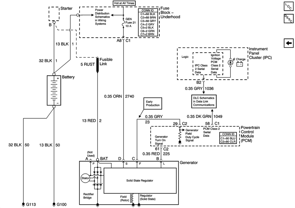
The generator provides voltage to operate the vehicle's electrical system and to charge its battery. A magnetic field is created when current flows through the rotor. This field rotates as the rotor is driven by the engine, creating an AC voltage in the stator windings. The AC voltage is converted to DC by the rectifier bridge and is supplied to the electrical system at the battery terminal.
When the engine is running, the generator turn-on signal is sent to the generator from the PCM, turning on the regulator. The generator's voltage regulator controls current to the rotor, thereby controlling the output voltage. The rotor current is proportional to the electrical pulse width supplied by the regulator. When the engine is started, the regulator senses generator rotation by detecting AC voltage at the stator through an internal wire. Once the engine is running, the regulator varies the field current by controlling the pulse width. This regulates the generator output voltage for proper battery charging and electrical system operation. The generator F terminal is connected internally to the voltage regulator and externally to the PCM. When the voltage regulator detects a charging system problem, it grounds this circuit to signal the PCM that a problem exists. The PCM monitors the generator field duty cycle signal circuit. The system voltage sense circuit receives battery positive voltage that is Hot At All Times through the GEN fuse in the rear fuse block. This voltage is used by the regulator as the reference for system voltage control.
Charging System Indicator
The IPC illuminates the charge indicator in the message center when the following occurs:
• The PCM detects that the generator output is less than 11 volts or greater than 16 volts. The IPC receives a class 2 message from the PCM requesting illumination.
• The IPC determines that the system voltage is less than 11 volts or greater than 16 volts. The IPC receives a class 2 message from the body control module (BCM) indicating the system voltage.
• The IPC performs the displays test at the start of each ignition cycle. The indicator illuminates for approximately 3 seconds.
• The ignition is ON, with the engine OFF.