Thread: CAD Drawing for the Gen V M90 output Flange...

Page 1 of 2 12 LastLast
Results 1 to 20 of 21
  1. #1 CAD Drawing for the Gen V M90 output Flange... 
    SE Level Member DamnedButDetermined's Avatar
    Join Date
    Dec 2012
    Location
    Jacksonville, FL
    Posts
    9
    Thanks (Received)
    0
    Likes (Received)
    0
    Dislikes (Received)
    0
    I do not have experience with the real CAD programs that CNC machines work with but I am pretty good with Sketchup. I did a to scale (as best I could) drawing of the mounting surface of the M90 and I was wondering if anyone knew how to turn that into a file that a cnc machine could read?

    Background on what I am trying to accomplish...
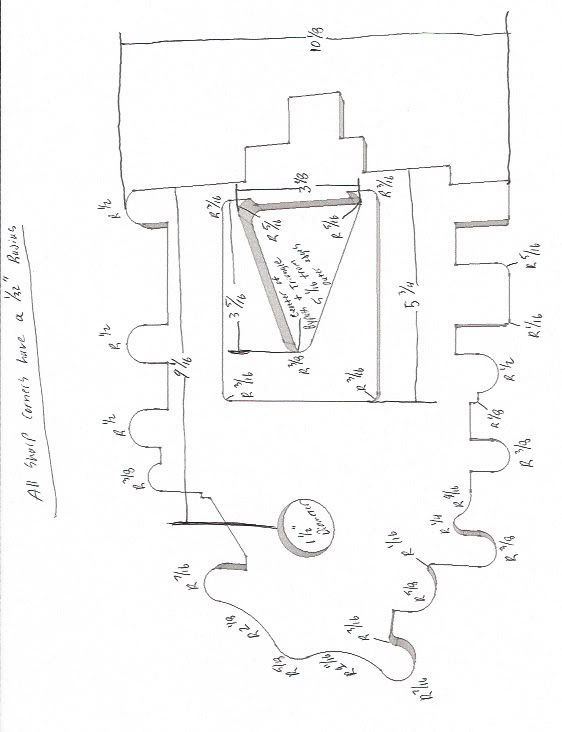
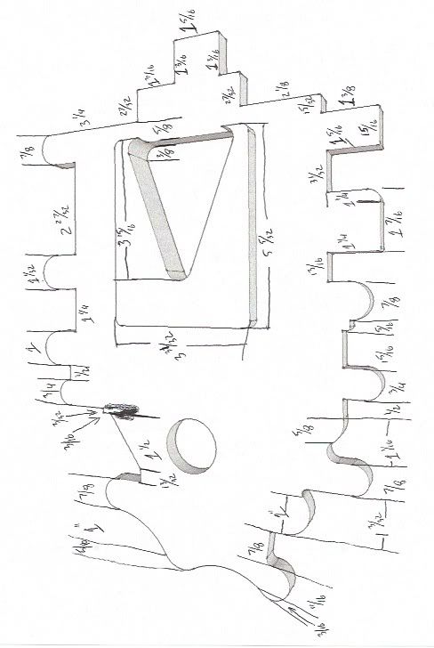
    I have a 240sx KA24DE engine that I am going to remote mount the M90 onto the exhaust side of the engine. I want to cnc a flange that will bolt up to the bottom of the M90 (minus all the coolant holes) and extend into the supercharger just enough to seal off the silencer holes and only leave the triangle outlet for an opening. I was then going to modify a 3" pipe to weld directly onto the triangle outlet and drill in a tee for the 1 1/2" bypass line to go back into the charger.

    I have attached a screenshot of the Sketchup File but if someone knows how to transfer it to CNC code then I can e-mail the file to them.

    Thanks for the help,
    Zac
    CAD Drawing for the Gen V M90 output Flange... Attached Images
    Reply With Quote  
     

  2. #2 Re: CAD Drawing for the Gen V M90 output Flange... 
    GT Level Member 88formula's Avatar
    Join Date
    Oct 2012
    Location
    West Branch, MI
    Posts
    341
    Thanks (Received)
    0
    Likes (Received)
    0
    Dislikes (Received)
    0
    Sounds like a great project, I have heard of people making these to go onto Northstar motors. If I had access to a cad program still I would help you out!
    Reply With Quote  
     

  3. #3 Re: CAD Drawing for the Gen V M90 output Flange... 
    SE Level Member DamnedButDetermined's Avatar
    Join Date
    Dec 2012
    Location
    Jacksonville, FL
    Posts
    9
    Thanks (Received)
    0
    Likes (Received)
    0
    Dislikes (Received)
    0
    Thanks...It is my VERY slowly evolving project Fellow 240 owners are getting 250hp 250tq out of the M62 so I am hoping to get around 325/325 out of this setup.

    Zac
    Reply With Quote  
     

  4. #4 Re: CAD Drawing for the Gen V M90 output Flange... 
    I live here. MoarkatsINmuhtrailer's Avatar
    Join Date
    Apr 2010
    Location
    Ohio
    Posts
    5,150
    Thanks (Received)
    0
    Likes (Received)
    0
    Dislikes (Received)
    0
    i need all measurements if you want me to make a program
    Reply With Quote  
     

  5. #5 Re: CAD Drawing for the Gen V M90 output Flange... 
    I live here. MoarkatsINmuhtrailer's Avatar
    Join Date
    Apr 2010
    Location
    Ohio
    Posts
    5,150
    Thanks (Received)
    0
    Likes (Received)
    0
    Dislikes (Received)
    0
    and i need to know what size stock you are starting from
    Reply With Quote  
     

  6. #6 Re: CAD Drawing for the Gen V M90 output Flange... 
    SE Level Member DamnedButDetermined's Avatar
    Join Date
    Dec 2012
    Location
    Jacksonville, FL
    Posts
    9
    Thanks (Received)
    0
    Likes (Received)
    0
    Dislikes (Received)
    0
    Quote Originally Posted by 99PGPGT View Post
    and i need to know what size stock you are starting from
    Dude you rock. I will get all the dimensions from the Sketchup drawing and post them here for you. As for stock material to start from I do not know this. I do not have the material so that would be determined by the machine shop. Does it matter a huge amount to know the start size from the beginning?

    Zac
    Reply With Quote  
     

  7. #7  
    I live here. MoarkatsINmuhtrailer's Avatar
    Join Date
    Apr 2010
    Location
    Ohio
    Posts
    5,150
    Thanks (Received)
    0
    Likes (Received)
    0
    Dislikes (Received)
    0
    Well as in how big of a piece of metal are we starting with? 1.5'x1'x1"
    Reply With Quote  
     

  8. #8  
    I live here. MoarkatsINmuhtrailer's Avatar
    Join Date
    Apr 2010
    Location
    Ohio
    Posts
    5,150
    Thanks (Received)
    0
    Likes (Received)
    0
    Dislikes (Received)
    0
    Quote Originally Posted by DamnedButDetermined View Post
    Dude you rock. I will get all the dimensions from the Sketchup drawing and post them here for you. As for stock material to start from I do not know this. I do not have the material so that would be determined by the machine shop. Does it matter a huge amount to know the start size from the beginning?

    Zac
    I'll have to convert them to CAD then write the program and test it to make sure it works. Now whatever shop you take the program to, may not be able to throw my program right into the machine and run it as that all cnc's have a different program guide. But most all program codes are very universal
    Reply With Quote  
     

  9. #9 Re: CAD Drawing for the Gen V M90 output Flange... 
    SE Level Member DamnedButDetermined's Avatar
    Join Date
    Dec 2012
    Location
    Jacksonville, FL
    Posts
    9
    Thanks (Received)
    0
    Likes (Received)
    0
    Dislikes (Received)
    0
    Okay this is going to be crude but I hope it shows all of the correct dimensions for you. If you need something else just ask. Now that I have been thinking about this more I think I want the main flange thickness to be 3/4" for added strength, and then the block-off plate/outlet raised section is an additional 1/2". I don't know if we should start off with a 1.25" thick block or go thicker and then machine down to the proper thickness? The starting block would be 12" x 16" to keep things simple.

    All sharp corners on the flange plate should receive a 1/32" radius to avoid injury!


    Reply With Quote  
     

  10. #10 Re: CAD Drawing for the Gen V M90 output Flange... 
    I live here. TLSheff's Avatar
    Join Date
    Dec 2009
    Location
    Durant, Oklahoma, United States
    Posts
    8,033
    Thanks (Received)
    0
    Likes (Received)
    0
    Dislikes (Received)
    0
    Not to thread jack or anything but why go through all of this?

    You could do a cheap custom turbo build for less headache and make more power, or LS1 swap and make 300+ hp/tq base.

    You can do what you want, just seems like a lot of extra work and time verses the easier options to me.

    Quote Originally Posted by AmericanSoldier View Post
    ...not scanning/monitoring your motor is like bangin a hooker and you just HOPE your not infected.
    Reply With Quote  
     

  11. #11 Re: CAD Drawing for the Gen V M90 output Flange... 
    DUI BABY Bio248's Avatar
    Join Date
    Jan 2008
    Location
    MILWAUKEE
    Posts
    31,340
    Thanks (Received)
    0
    Likes (Received)
    1
    Dislikes (Received)
    0
    Quote Originally Posted by TLSheff View Post
    Not to thread jYou can do what you want, just seems like a lot of extra work and time verses the easier options to me.
    apparently you're not an enthusiast.

    it's all about trying something different and fun, even if it's harder and more expensive.
    Reply With Quote  
     

  12. #12 Re: CAD Drawing for the Gen V M90 output Flange... 
    I live here. TLSheff's Avatar
    Join Date
    Dec 2009
    Location
    Durant, Oklahoma, United States
    Posts
    8,033
    Thanks (Received)
    0
    Likes (Received)
    0
    Dislikes (Received)
    0
    I am a very big enthusiast. Just considering the alternatives I was curious why the OP was going THIS route. Most tend to do a SBC swap with a LM7 or LS1 which can be done for less than $1500 if you know how to turn a wrench... or a turbo swap if you have the couple grand to throw at it.

    Quote Originally Posted by AmericanSoldier View Post
    ...not scanning/monitoring your motor is like bangin a hooker and you just HOPE your not infected.
    Reply With Quote  
     

  13. #13 Re: CAD Drawing for the Gen V M90 output Flange... 
    SE Level Member DamnedButDetermined's Avatar
    Join Date
    Dec 2012
    Location
    Jacksonville, FL
    Posts
    9
    Thanks (Received)
    0
    Likes (Received)
    0
    Dislikes (Received)
    0
    Quote Originally Posted by TLSheff View Post
    Not to thread jack or anything but why go through all of this?

    You could do a cheap custom turbo build for less headache and make more power, or LS1 swap and make 300+ hp/tq base.

    You can do what you want, just seems like a lot of extra work and time verses the easier options to me.
    The extra work doesn't bother me and the costs are going to be less than an LSX swap if I keep bargain hunting. So far it is just...
    $150 for the Gen V M90
    est $175 for the output flange
    est $300 for the rest of the piping
    $375 for water:air intercooler
    $300 injectors
    $700 Megasquirt ECU
    $400 headers and exhaust
    So around $2400 for this idea. There is no way I can see an LSX swap coming in for under that amount. Everything is just way too expensive when going that route unless you buy subpar parts.

    As for turbo I know I could end up with MONSTER hp but I want instant torque instead. The supercharger is much easier to control boost pressure unlike a turbo with chance of boost spike. I was going to go Holset turbo mode, but changed it up for M90 power

    Zac
    Reply With Quote  
     

  14. #14 Re: CAD Drawing for the Gen V M90 output Flange... 
    SE Level Member DamnedButDetermined's Avatar
    Join Date
    Dec 2012
    Location
    Jacksonville, FL
    Posts
    9
    Thanks (Received)
    0
    Likes (Received)
    0
    Dislikes (Received)
    0
    Never mind I changed my mind! Continue as usual
    Zac
    Last edited by DamnedButDetermined; 12-06-2012 at 04:09 PM.
    Reply With Quote  
     

  15. #15 Re: CAD Drawing for the Gen V M90 output Flange... 
    I live here. MoarkatsINmuhtrailer's Avatar
    Join Date
    Apr 2010
    Location
    Ohio
    Posts
    5,150
    Thanks (Received)
    0
    Likes (Received)
    0
    Dislikes (Received)
    0
    Reply With Quote  
     

  16. #16 Re: CAD Drawing for the Gen V M90 output Flange... 
    I live here. MoarkatsINmuhtrailer's Avatar
    Join Date
    Apr 2010
    Location
    Ohio
    Posts
    5,150
    Thanks (Received)
    0
    Likes (Received)
    0
    Dislikes (Received)
    0
    oh...and the top right radius where it says 7/8 across...how does it have a 1/2" radius???
    Reply With Quote  
     

  17. #17 Re: CAD Drawing for the Gen V M90 output Flange... 
    SE Level Member DamnedButDetermined's Avatar
    Join Date
    Dec 2012
    Location
    Jacksonville, FL
    Posts
    9
    Thanks (Received)
    0
    Likes (Received)
    0
    Dislikes (Received)
    0
    Top question mark is 3/4"
    Bottom question mark is 9/16?

    That radius is 1/2" even though the stub is only 7/8" wide. The center of the 1/2" radius is based off of the point where the curve meets the 3/4" (top question mark) endpoint.

    I hope that clears that up for you.
    Zac
    Reply With Quote  
     

  18. #18  
    I live here. MoarkatsINmuhtrailer's Avatar
    Join Date
    Apr 2010
    Location
    Ohio
    Posts
    5,150
    Thanks (Received)
    0
    Likes (Received)
    0
    Dislikes (Received)
    0
    Yeahh, with knowing the 3/4 dimension it does.

    How sure are you on the 9/16?
    Reply With Quote  
     

  19. #19 Re: CAD Drawing for the Gen V M90 output Flange... 
    SE Level Member DamnedButDetermined's Avatar
    Join Date
    Dec 2012
    Location
    Jacksonville, FL
    Posts
    9
    Thanks (Received)
    0
    Likes (Received)
    0
    Dislikes (Received)
    0
    I dropped off the M90 as a friends house so I can't double check on that right now. That length is not a crucial measurement so it can be anything you want it to be (within reason) that makes this works. I guess some of my dimensions are not figuring out correctly?

    Zac
    Gen III M90 for sale! PM me for price...
    Reply With Quote  
     

  20. #20 Re: CAD Drawing for the Gen V M90 output Flange... 
    Turbo is the way to go. BillBoost37's Avatar
    Join Date
    Jul 2009
    Location
    W Spfld
    Posts
    26,815
    Thanks (Received)
    53
    Likes (Received)
    90
    Dislikes (Received)
    1
    Some of us have V and 3 laying around if you guys need something else.
    I drink..so consider that when reading my posts.

    2010 Audi A6 Dual IC's
    Reply With Quote  
     

Page 1 of 2 12 LastLast

Similar Threads

  1. Fuel pump drawing to many amps?
    By Lukesgrandprix in forum 3.8L V6 Naturally Aspirated (L36)(L26)
    Replies: 0
    Last Post: 02-24-2012, 06:36 PM
  2. my friends grand prix drawing
    By gtman98 in forum Off Topic Discussion
    Replies: 10
    Last Post: 11-04-2008, 03:59 PM
  3. LF CAD drawing
    By 04DetroitLS in forum Off Topic Discussion
    Replies: 6
    Last Post: 10-03-2008, 01:35 PM
Tags for this Thread

View Tag Cloud

Bookmarks
Bookmarks
Posting Permissions
  • You may not post new threads
  • You may not post replies
  • You may not post attachments
  • You may not edit your posts
  •