Thread: How To: Build an offboard PCM interface

Page 1 of 3 123 LastLast
Results 1 to 20 of 43
  1. #1 How To: Build an offboard PCM interface 
    GTX Level Member
    Join Date
    Aug 2010
    Location
    Minnesota
    Posts
    1,409
    Thanks (Received)
    0
    Likes (Received)
    0
    Dislikes (Received)
    0
    This is a work in progress thread but here is a list of materials (prices may have changed):

    Offboard:

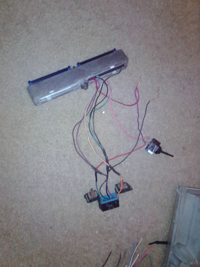
    -Project box: $3.99 + tax

    Project Enclosure (5x2.5x2) : Project Boxes | RadioShack.com

    -LED switch: $3.99 + tax

    SPST 12VDC/20A Illuminated Toggle Switch with Red LED : Toggle Switches | RadioShack.com

    -Power supply: $7.99 + free shipping

    12V 5V AC Adapter Power Supply HDD Hard Disk Drive IDE | eBay

    -Female Spade connectors: $1.99 + tax

    Female Crimp-On Quick-Disconnects (10-Pack) : Disconnects | RadioShack.com

    -Wire Loom: $1.99 + tax

    Buchanan 3/8 in. Split Flexible Tubing Connector-772240 at The Home Depot

    -3ft 14AWG Power Cord Cable w/ 3 Conductor PC Power Connector Socket (C13/5-15P) - Black: $4.04 Shipped

    For only $1.64 each when QTY 50+ purchased - 3ft 14AWG Power Cord Cable w/ 3 Conductor PC Power Connector Socket (C13/5-15P) - Black

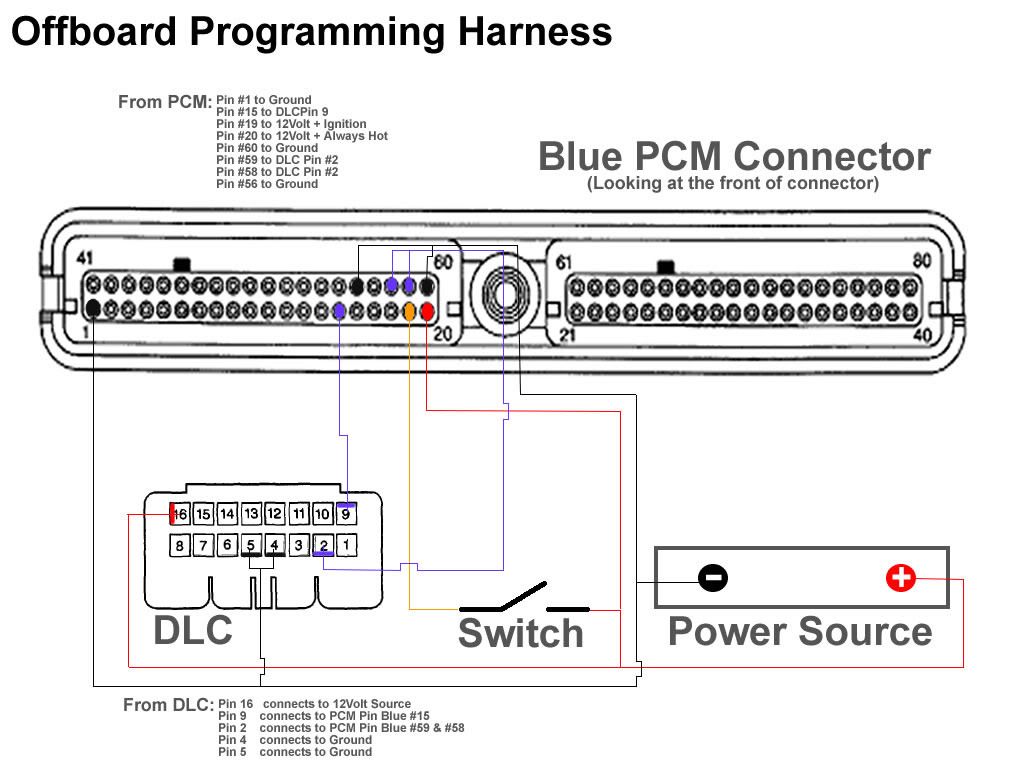
    -PCM blue connector: $10.00 + tax

    -Bought at the junk yard

    OBD II Connector: $5.00 + tax

    -Bought at the junk yard

    2 bolts, 4 washers, 2 nuts: $1.40+ tax

    Last edited by Pure2sin; 07-29-2013 at 08:57 PM.
    Reply With Quote  
     

  2. #2 Re: How To: Build an offboard PCM interface 
    Turbo is the way to go. Fivefingerdeathpunch's Avatar
    Join Date
    Sep 2009
    Location
    Rogers, MN
    Posts
    21,030
    Thanks (Received)
    21
    Likes (Received)
    45
    Dislikes (Received)
    0
    This kinda stuff reminds me of the megasquirt boards in a way.

    What will you be using it for?

    SMGPFC Member #1
    Reply With Quote  
     

  3. #3 Re: How To: Build an offboard PCM interface 
    GTX Level Member
    Join Date
    Aug 2010
    Location
    Minnesota
    Posts
    1,409
    Thanks (Received)
    0
    Likes (Received)
    0
    Dislikes (Received)
    0
    Monte Carlos have been known to have trouble with having to pull the radio fuse to flash the PCM. I just had an issue where I almost bricked my PCM because I didn't notice the battery was low. I have two PCMs so one will always be in the car and the other will be for new files then swapped in. Just will make it easier for me personally I guess.

    It could always be used to write to other PCMs if anyone wanted to tune PCMs for other peoples cars as well.
    Reply With Quote  
     

  4. #4 Re: How To: Build an offboard PCM interface 
    Turbo is the way to go. BillBoost37's Avatar
    Join Date
    Jul 2009
    Location
    W Spfld
    Posts
    26,833
    Thanks (Received)
    53
    Likes (Received)
    90
    Dislikes (Received)
    1
    Let's not forget that while you are building an offboard for a 97-03 pcm, you can also wire up the newer 04+ connector as well. Switch isn't required, since you can plug and unplug it. It's nice to have thought.

    I used an old pc power supply, use the switch on the back of it and poof.. works all the same and I robbed it from something for free.

    Even funnier is that WOTGTP contacted me last night looking to sell one. If you need one, toss him a pm.
    I drink..so consider that when reading my posts.

    2010 Audi A6 Dual IC's
    Reply With Quote  
     

  5. #5 Re: How To: Build an offboard PCM interface 
    GT Level Member KoldAsIce's Avatar
    Join Date
    Mar 2013
    Location
    Staten Island, NY
    Posts
    306
    Thanks (Received)
    0
    Likes (Received)
    0
    Dislikes (Received)
    0
    Bill can you get in touch with WOTGTP? I messaged him about the offboard unit and he never replied I don't know if he sold it or whatever :/ I want one.. Thanks
    ZZP 10.3mm Wires, Autolite 605s, CAI, HP Tuners PCM,
    3" Catted DP, Straight Piped, 20% Tint, 5k HIDs, 6k Fogs
    220a (eBay) Alt , RF Prime Amp 1333w (RMS), Kicker 12" L7 750w (RMS), RF PBR Amp 75w (RMS x4)
    Alpine Type R (Front 5.25" 90w (RMS Each), Rear 6"x9" 100w (RMS Each)

    Reply With Quote  
     

  6. #6 Re: How To: Build an offboard PCM interface 
    GTP Level Member 231FUN's Avatar
    Join Date
    Dec 2011
    Location
    Ontario,Canada
    Posts
    861
    Thanks (Received)
    0
    Likes (Received)
    0
    Dislikes (Received)
    0
    Quote Originally Posted by KoldAsIce View Post
    Bill can you get in touch with WOTGTP? I messaged him about the offboard unit and he never replied I don't know if he sold it or whatever :/ I want one.. Thanks
    You realize that was over a year ago eh...
    Build one or put a post up in the wanted classified ads, there are a couple people here that have recently or are going to build one so maybe you can see if one of them can build you one if you don't feel you can take on the project yourself.
    Reply With Quote  
     

  7. #7 Re: How To: Build an offboard PCM interface 
    GT Level Member KoldAsIce's Avatar
    Join Date
    Mar 2013
    Location
    Staten Island, NY
    Posts
    306
    Thanks (Received)
    0
    Likes (Received)
    0
    Dislikes (Received)
    0
    No but he posted it for sale this month I know that this was a year ago
    ZZP 10.3mm Wires, Autolite 605s, CAI, HP Tuners PCM,
    3" Catted DP, Straight Piped, 20% Tint, 5k HIDs, 6k Fogs
    220a (eBay) Alt , RF Prime Amp 1333w (RMS), Kicker 12" L7 750w (RMS), RF PBR Amp 75w (RMS x4)
    Alpine Type R (Front 5.25" 90w (RMS Each), Rear 6"x9" 100w (RMS Each)

    Reply With Quote  
     

  8. #8 Re: How To: Build an offboard PCM interface 
    Killa Bee Scottydoggs's Avatar
    Join Date
    Aug 2010
    Location
    new jersey
    Posts
    39,997
    Thanks (Received)
    63
    Likes (Received)
    166
    Dislikes (Received)
    5
    its super easy to make. i just made one. also just pulled a old pc power supply out of the case. google / you tube says the yellow wire is 12 volts. any black is ground.


    worked like a charm sat morning.

    98 Buick Regal GS, F body brakes, Caddy STS wheels, tinted tails L36 bottom end, lightly ported heads, 1.95 roller rockers, headers, gen 5 N* 3.0 pulley, FSIC, 42 lb injectors, a BrandonHall rebuilt trans, DHP tuned and AEM water/Meth injection https://goo.gl/gpV5kW
    Reply With Quote  
     

  9. #9 Re: How To: Build an offboard PCM interface 
    GXP Level Member Turbocharged400sbc's Avatar
    Join Date
    Jan 2008
    Location
    hangover park IL
    Posts
    2,714
    Thanks (Received)
    4
    Likes (Received)
    11
    Dislikes (Received)
    0
    just get a 4 diode rectifier and your golden. made this for 04+ but ive added a 96-03

    i love ****ing with people and connecting it to the battery backwards

    ~James~ Psychotic Gearhead
    projects: 84 Cressida waGN~ 90 LN3 3800, equal length headers, T70, 89 700r4, misc parts,
    1994 Oldsmobile 442 (462ci-4wd-2 engines) L67/4t80e^2,
    00 Turbo Regal 608 fwhp 575ftlbs at 5500rpm, 98 WhippledRiv, 97 GTP
    Reply With Quote  
     

  10. #10 Re: How To: Build an offboard PCM interface 
    Killa Bee Scottydoggs's Avatar
    Join Date
    Aug 2010
    Location
    new jersey
    Posts
    39,997
    Thanks (Received)
    63
    Likes (Received)
    166
    Dislikes (Received)
    5
    looks like this when done. now that i have the power supply im gonna buy a two side plug to plug the off board into the p/s. so its not rigged up twisting them together. my switch has no on / off labeled on it, so i marked it.


    being that it looks like your tuning now. dhp can and will brick your pcm someday. its a risk. so what i would do if i was you is to go to a junk yard, find a year car your car can use the pcm from, buy the whole air box, cut the wires to the pcm plug, rip the obd2 port out the car, and drop it all in the air box. now go pay for that air box lol i bought 2 air boxes for 12 each. one had the pcm plugs and all in it, the other just the pcm.

    this way you can flash a stock tune to it, and have a back up, or flash your last known good tune to it, as a back up. you can also change the vin# in the pcm you your # in vin maintenance.

    98 Buick Regal GS, F body brakes, Caddy STS wheels, tinted tails L36 bottom end, lightly ported heads, 1.95 roller rockers, headers, gen 5 N* 3.0 pulley, FSIC, 42 lb injectors, a BrandonHall rebuilt trans, DHP tuned and AEM water/Meth injection https://goo.gl/gpV5kW
    Reply With Quote  
     

  11. #11 Re: How To: Build an offboard PCM interface 
    Solving problems BrandonHall10's Avatar
    Join Date
    Mar 2014
    Location
    Tucson
    Posts
    3,167
    Thanks (Received)
    10
    Likes (Received)
    146
    Dislikes (Received)
    3
    Okay. I'm looking to make one of these for myself, and I think I understand what's going on here. I have my PCM plug, and OBD2 port in hand. The rest I will get next time I'm by a radio shack.

    So here's my question;
    All my wires and numbers for the PCM plug jive except #56 (ground). There's no lead from #56. Safe to assume I'm okay without it, because #56 and #60 run together to ground? FWIW, I did get the PCM plug from a GP.
    Reply With Quote  
     

  12. #12 Re: How To: Build an offboard PCM interface 
    Killa Bee Scottydoggs's Avatar
    Join Date
    Aug 2010
    Location
    new jersey
    Posts
    39,997
    Thanks (Received)
    63
    Likes (Received)
    166
    Dislikes (Received)
    5
    you pull all the wires form the pcm plug, then pick the fat wires and re pin only where you need a wire. does that makes sense?

    the pcm plug has to be taken apart.

    98 Buick Regal GS, F body brakes, Caddy STS wheels, tinted tails L36 bottom end, lightly ported heads, 1.95 roller rockers, headers, gen 5 N* 3.0 pulley, FSIC, 42 lb injectors, a BrandonHall rebuilt trans, DHP tuned and AEM water/Meth injection https://goo.gl/gpV5kW
    Reply With Quote  
     

  13. #13 Re: How To: Build an offboard PCM interface 
    Solving problems BrandonHall10's Avatar
    Join Date
    Mar 2014
    Location
    Tucson
    Posts
    3,167
    Thanks (Received)
    10
    Likes (Received)
    146
    Dislikes (Received)
    3
    It does. I planned on pulling all the unused leads. Didn't think about stabbing one back in #56. Thanks!
    Reply With Quote  
     

  14. #14 Re: How To: Build an offboard PCM interface 
    Killa Bee Scottydoggs's Avatar
    Join Date
    Aug 2010
    Location
    new jersey
    Posts
    39,997
    Thanks (Received)
    63
    Likes (Received)
    166
    Dislikes (Received)
    5
    if the diagram says to put a wire there do it, you may have to poke a hole in that rubber part the wires go through.

    you have the plug apart yet? its a bit tricky, i can direct you how to do that with out breaking it if need be. i can take some pics of how to do it easy enough.

    98 Buick Regal GS, F body brakes, Caddy STS wheels, tinted tails L36 bottom end, lightly ported heads, 1.95 roller rockers, headers, gen 5 N* 3.0 pulley, FSIC, 42 lb injectors, a BrandonHall rebuilt trans, DHP tuned and AEM water/Meth injection https://goo.gl/gpV5kW
    Reply With Quote  
     

  15. #15 Re: How To: Build an offboard PCM interface 
    Solving problems BrandonHall10's Avatar
    Join Date
    Mar 2014
    Location
    Tucson
    Posts
    3,167
    Thanks (Received)
    10
    Likes (Received)
    146
    Dislikes (Received)
    3
    I have not had the plug apart. I tried to take another one apart but couldn't because of that screw. I hoped to just jab that seal out of #56 and poke another lead through. Assuming the end stays on at least one of the pulled leads.
    Reply With Quote  
     

  16. #16 Re: How To: Build an offboard PCM interface 
    Killa Bee Scottydoggs's Avatar
    Join Date
    Aug 2010
    Location
    new jersey
    Posts
    39,997
    Thanks (Received)
    63
    Likes (Received)
    166
    Dislikes (Received)
    5
    ok you just stop there. ill post some pics before you break it lol that plug is like 3 parts that all need to come apart. you need to push a clip inside with a awl or pick to release the wires from the plug once its apart.

    ill take pics and post em tomorrow, im off to bed.

    98 Buick Regal GS, F body brakes, Caddy STS wheels, tinted tails L36 bottom end, lightly ported heads, 1.95 roller rockers, headers, gen 5 N* 3.0 pulley, FSIC, 42 lb injectors, a BrandonHall rebuilt trans, DHP tuned and AEM water/Meth injection https://goo.gl/gpV5kW
    Reply With Quote  
     

  17. #17 Re: How To: Build an offboard PCM interface 
    Solving problems BrandonHall10's Avatar
    Join Date
    Mar 2014
    Location
    Tucson
    Posts
    3,167
    Thanks (Received)
    10
    Likes (Received)
    146
    Dislikes (Received)
    3
    Standing by for pics.
    Reply With Quote  
     

  18. #18 Re: How To: Build an offboard PCM interface 
    Turbo is the way to go. BillBoost37's Avatar
    Join Date
    Jul 2009
    Location
    W Spfld
    Posts
    26,833
    Thanks (Received)
    53
    Likes (Received)
    90
    Dislikes (Received)
    1
    I pulled all the wires out except grounds, power and the two data lines. Connected data to the obd2, put power and ground to the power supply.. poof done.
    I drink..so consider that when reading my posts.

    2010 Audi A6 Dual IC's
    Reply With Quote  
     

  19. #19 Re: How To: Build an offboard PCM interface 
    GXP Level Member Turbocharged400sbc's Avatar
    Join Date
    Jan 2008
    Location
    hangover park IL
    Posts
    2,714
    Thanks (Received)
    4
    Likes (Received)
    11
    Dislikes (Received)
    0
    you don't actually have to remove the rest of the pins in many cases there are several connection points for power and ground depending on the model of car even with the same 7440 hardware number PCM.
    all you have to do is get a pic and open up the pins so that they no longer grab onto the PCM pins you don't actually have to remove all of them
    ~James~ Psychotic Gearhead
    projects: 84 Cressida waGN~ 90 LN3 3800, equal length headers, T70, 89 700r4, misc parts,
    1994 Oldsmobile 442 (462ci-4wd-2 engines) L67/4t80e^2,
    00 Turbo Regal 608 fwhp 575ftlbs at 5500rpm, 98 WhippledRiv, 97 GTP
    Reply With Quote  
     

  20. #20 Re: How To: Build an offboard PCM interface 
    Killa Bee Scottydoggs's Avatar
    Join Date
    Aug 2010
    Location
    new jersey
    Posts
    39,997
    Thanks (Received)
    63
    Likes (Received)
    166
    Dislikes (Received)
    5
    why have 40 wires all over when all you need is 5? and why use them thin wires when you can pull them all out, and use only the fat wires. its a lot easier in my eyes, to strip the plug, then install the ones needed, vs taking the unused ones by one in the birds nest.

    you try to help yet you make it sound harder. the diagram shows us where to put the ground, if you want to trust your own ground, "you" do so, dont tell some one to find a new ground cause your lazy or something. ( you dont even say what pin, just others????) < thats not help.

    98 Buick Regal GS, F body brakes, Caddy STS wheels, tinted tails L36 bottom end, lightly ported heads, 1.95 roller rockers, headers, gen 5 N* 3.0 pulley, FSIC, 42 lb injectors, a BrandonHall rebuilt trans, DHP tuned and AEM water/Meth injection https://goo.gl/gpV5kW
    Reply With Quote  
     

Page 1 of 3 123 LastLast
Tags for this Thread

View Tag Cloud

Bookmarks
Bookmarks
Posting Permissions
  • You may not post new threads
  • You may not post replies
  • You may not post attachments
  • You may not edit your posts
  •