This.Originally Posted by Scottydoggs

It would drive me crazy having all those cut wires just floating around.

|
|


This.
It would drive me crazy having all those cut wires just floating around.


here ya go guys.
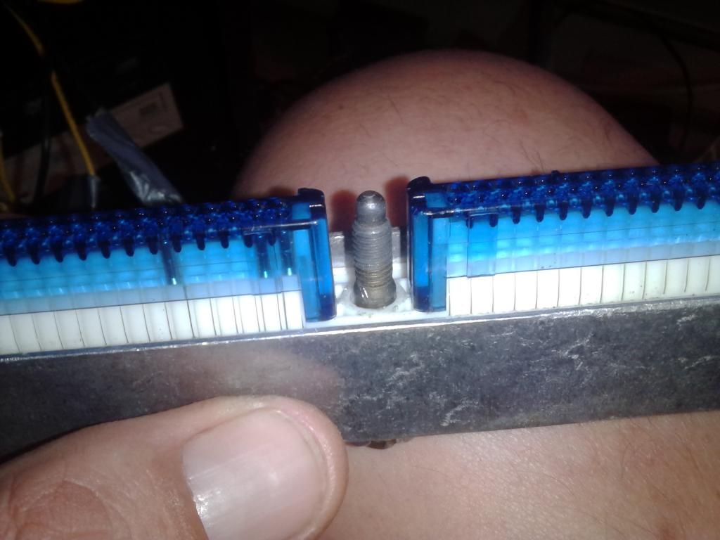
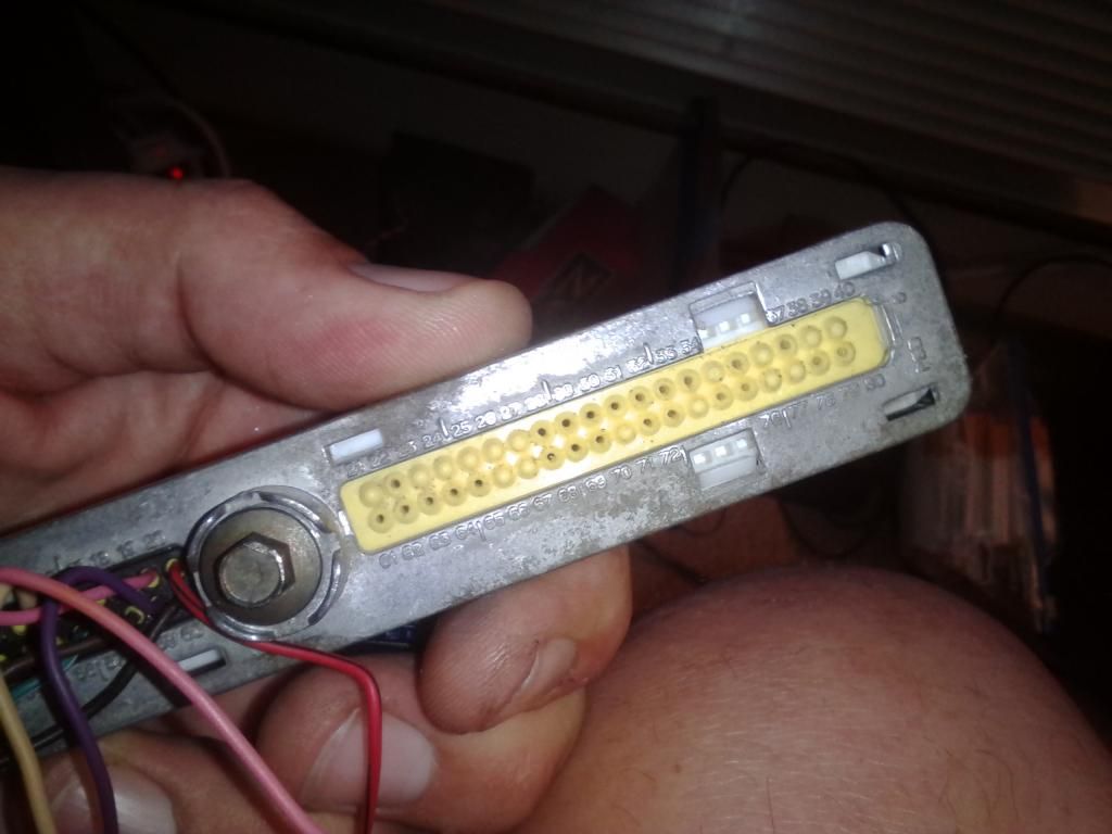
this bolt that bolts the the plug to the pcm, it has a lock washer on the end between the plugs. you need to get needle nose pliers, small dykes, what ever you have, then cut twist and remove it, or the bolt wont come out. be careful you dont break the blue caps.
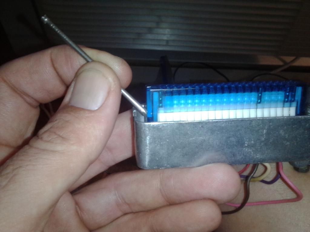
the blue caps, you push in from each side bottom to release it, (one side at a time. you'll see a slot in the cap push the white under the cap.
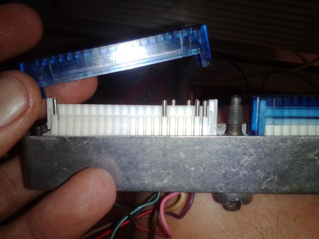
you'll see these white clips on the back side, pinch them, push the guts out.
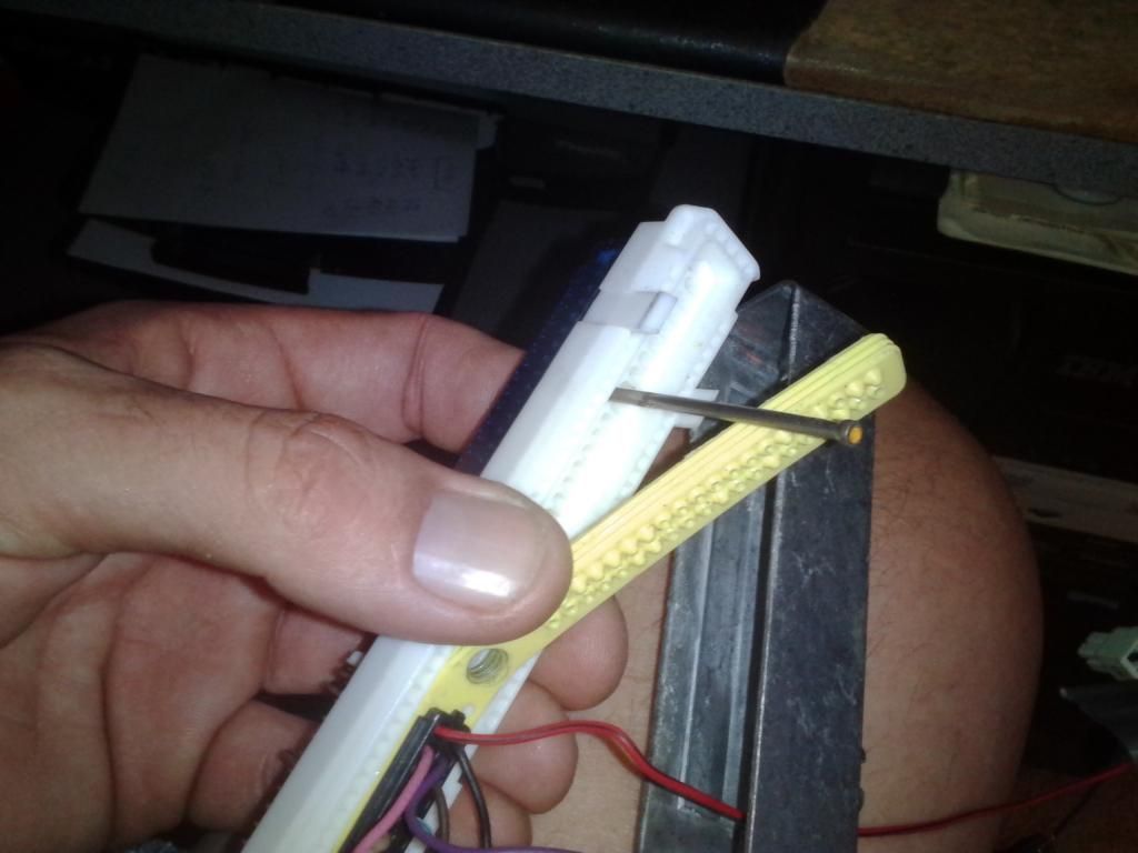
to release the pinned wires you remove the black rubber pad you see on the left side, i put that one back in on the side all the wires are on. then the yellow rubber part, then with a thin pick push in next tot he wire, push the wire in and then back out, may take a wiggle, but it will come out.
once the pinned wire is free, it can be pulled out, or pushed up and out. dont matter.
once the plug is stripped clean, pick fat wires from the mess laying on the floor now. and push them in as shown on the diagram from the bottom, make sure you feel it click into place. you can also color code them best you can with the wires, pink for ignition, red for power, blacks for grounds. see my top two wires, one red one pink? those are power and a ignition wires.
have at it.
Last edited by Scottydoggs; 10-08-2014 at 08:26 AM.


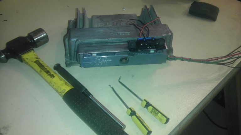
FWIW a small socket that doesn't fit over the bolt and a hammer work great for bolt removal.


I just cut the wires off at the connector no reason to let em stick out or anything but I'm not going to sit there for no reason and pop all that s*** out when all I gotta do is snip a bunch and be done with it.
look up the wiring diagrams for PCMs as far back as 96 all the way to 2003 all the platforms and you will find there are three variations of power and ground feeds to the PCM when you take a multimeter and check the pins of these terminals you will find that multiple pins are connected to each other ground pin xxx is also connected to ground pin xyy. ..switched power pins are also connected to other switched our pins same with the hot feeds
why do you think an off board someone wired up for Grand Prix still works on a Park Avenue or on a 96 Grand Am I'm pretty sure those people did not re-pin their off boards
I'd still also highly recommend getting a diode rectifier for your power source... it doesn't happen often but there are times that people hook up the connections backwards and you really don't wanna f*** anything up...a 4 diode rectifier at Radio Shack is 10 bucks and significantly reduces the chance for f*ckage
if you want a sloppy off board do it your way.
and this is gp board, not a park ave or whatever board, this is what works for most of us, regal, or gp. we dont need to tune those other cars or look up how to make a off board for them.
i dont see you points here at all. follow that diagram and it will work for us 97-03 guys.
As far as leaving wires in, or taking them out... To each their own. There is no wrong way. God bless America, we get to do what we want. The only reason to pull them out, is to not have to look at them. Aesthetics. That is exactly my reason. If someone wants to leave them in and just cut them short, I'm not mad.
Tell me more about this 4 diode rectifier thing.
Well, I think I got it. I used some different colors, but I managed to keep the grounds black and the 12v+ red. All my data lines are green and my switched 12v is purple.
Thanks Scotty!!
Bill,
I ended up using the hammer and punch seen in the picture. Same thing I tried before with no success. I guess I just needed to hear someone say that was okay. I wasn't being aggressive enough. I tried using a pick and pliers to get that washer off. Lets just say, I'm better with a hammer!
double check the wires on the obd2 port that they are right, if you look close at the back side its numbered, i had to move one. or i read it wrong moved it and moved it back, one or the other. all i remember is i took one wire out and back in.
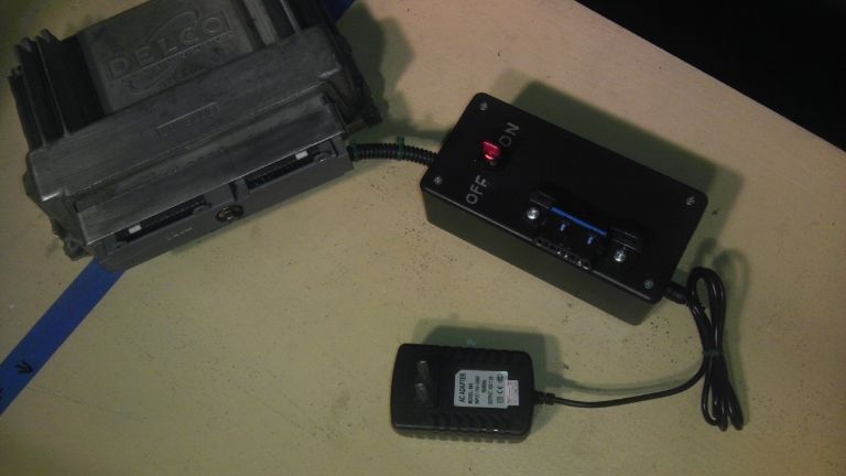
then all you need is a power source and a switch.
oh. if you ditch that grey plastic cover on the back side, you can bolt the obd2 port to the metal frame on the side with no wires through it. makes it look clean like that. and easy to use with no wires all over. you'd just have the neg and pos wires leading from both plugs and the switch.
some people dont even use a switch, just hard wire those wires with no switch. its your call there. i like the switch.
I was thinking of using a small project box as a "base." I'd leave the wires from the PCM plug they way they are, but wrap them in that plastic loom stuff and run it into the box. I'd then mount the OBD2 port and the switch to the box. Super clean. Probably do something like this for power:
http://www.amazon.com/gp/product/B00...A29H9ZXM6Z907A
Mount the adapter inside and drill a hole for the plug to go through so all you would see is the female end of the adapter. Also, the plug would be removable.
Just thinking out loud...
sounds pretty good to me.
yup sloppy ass ****. i clipped the terminal wires off flush with the connector, and jammed a pick in em to open em up (the bolt free 02 conn still has several that arent opened up to keep the connector held in place.
im just pointing out that if your finding pcm connectors that arent lining up, just use the diagram for the donor, snip wires, be on your way. your reworking the **** out of a connector, labor that should go towards more important parts of the project.
its a diode cluster rectifier...not much else to say, its cheap, wire up the output to offboard, put inputs to alligator clips for the battery. dont even have to label em (id did mine since my led droplights use the same connector and they run off a car battery quite well (it also allows me to use the offboard with my lights 12v 110v power supply and connector...kill 3 birds, one connector
if ya keep the switches, make sure they are well protected, inside a recess. my switches can only be turned off by a finger sized object. if someone dropped a cylinder head on it it would only turn the switch on, and never off.
to each their own
btw if you want the lazy way AND the fat wires, look for the 98 and earlier pcm connectors...them 96's actually used proper sized wire before gm cut the costs by cutting the copper down, since cars required more and more wire each year.
i cant be the only guy that noticed the pcm pinout differences and actually investigated the pcm pin connections am i?

I wish I had this type of know-how and skills :P There no way I would attempt this myself (I would ruin it, with my luck)!
Finally got around to finishing what I started. Here's the "finished" product:
I verified functionality using my scan tool. Now I just need a tuner!!
FWIW if you remove the bolt, it's much easier to put on/take off. It's a speed thing, not anything else.
Thanks for the writeup - worked like a charm!
- Steve

Also filing off the guide tabs on the blue make it work with the 97-98 ls1 pcm's
Sent from my SM-N920P using Tapatalk
Anyone have a diagram for the '04+ PCM?
| « Previous Thread | Next Thread » |
| Tags for this Thread |
| Bookmarks |
Bookmarks |