thats how it works, needs a cd in there, or a tape, depending on where you tapped in.

|
|


thats how it works, needs a cd in there, or a tape, depending on where you tapped in.


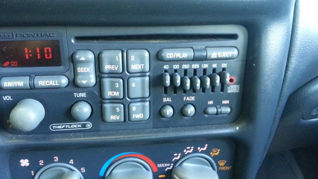
I have done this mod on 2 radios. One was the original deck that came in my 02 GTP, the the other was a deck I pulled from a 2002 ish S10. Both CD player have developed issues playing CD's, inert disk and a few seconds later the player spits it out and display reads 'ERR'. Has anyone had any luck with fixing the CD players? I may go to the junk yard and get a new disk drive to swap into my head unit.
thats cause its a old radio. new drive should fix it up. i got them codes way before i did the aux install. and still do. my cd wont play if its real cold out too. gets a E 20 code on the screen or something like that and spits out the cd. once the inside of the car is heated up it works fine.
truth is i went through my tape deck not the cd. tape still works like a champ.
I have a cassette and cd changer set up, the cd aspect doesnt work, i press play and it says cd for a few seconds then changes back to fm radio. Would this mod work?


Probably not through the broken CD module. It has to be able to play a CD to continue accepting audio from it. It would work on the cassette player.
Damn, so there's no way to do this, i might consider replacing the unit after all
you can use the tape deck. its how i did mine.

The GP I have with the cassette deck radio (with the EQ) is parked for the winter.
I am going to try adding this input jack.
Were either the ribbons and wires used on specific years, rather than splicing into the ribbon would an earlier HU from a junk yard be usable. Could a hack be used to install a later model with a built in Aux input be used to get around the vin theft system.
I don't know if they were used in specific years or certain model radios. Do you know what yours is yet? Check before trying to get another radio. Even still its completely doable but requires some skill with soldering, as well as a good soldering setup. Theftloc could be bypassed with a code calling a certain number, idk if it works anymore.
Think i'm gonna give this try on my single disc cd player. If I understand right I should use the 4th and 5th pin to tape into the radio part so I wouldn't need a CD in the player. Then use the 2nd pin for ground. Do I have this right? I assume the 4th pin is for left and the 5th pin is right, not sure if thats right


really like this one. I think bluetooth would be an awesome add-on too.
https://www.google.com/search?q=add+...w=1920&bih=955

Does anybody know when the ribbon cable was replaced with the connector style? And there doesn't need to be a wire grounded to the frame? Just solder the grounds on each side, connect them into 1 wire, and then solder that wire to the jack, that's it?

StayFree - clear out your mailbox
Hopefully that worked, I deleted my inbox and outbox.Originally Posted by kewGTP


I was getting ready to fix my lights and while searching the forum ran across this thread. As I am looking to see if it address two questions I have, I saw this post and even though it is old, I thought incase someone else runs into this issue, I might make a suggestion.
I wish I had a picture to look at, but usually the heat will lift a pad. It basically breaks down the glue that was holding the traces. Depending on how far back, sometimes you can fix it by carefully scraping some of the "green" off the attached etch exposing some copper. Then if you can bend the lead without shorting anything, or attach a jumper wire over to the lead.

Dont mean to bump a super old thread but I am planning on doing this mod. Do you still have the pictures? Photobucket has eaten them.
I do have them on my hard drive at home. I'll try to get them uploaded somewhere else
Sent from my SM-G930T using Tapatalk
Ok cool thank you.
| « Previous Thread | Next Thread » |
| Bookmarks |
Bookmarks |